2.3 Tree Diagram Editor
The Tree Diagram Editor is the primary modeling window within TreeAge Pro. You create the model structure within the Tree Diagram Editor by adding, editing, moving and deleting nodes. Changes made within an editor are not saved until you instruct TreeAge Pro to save the model document.
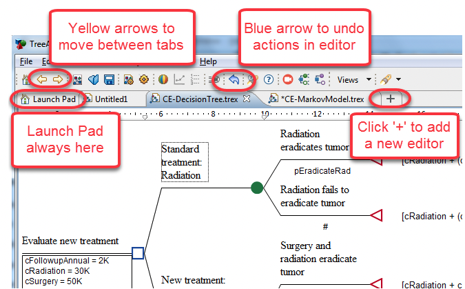
You can open multiple models at once, and each will be presented within a different Tree Diagram Editor tab within the overall pane.
The Launch Pad is always the left-most tab. The "+" option to create a new model is always the right-most tab.
To maximize the size of the Tree Diagram Editor, double-click on the tree editor tab. (This works for any of the Views in TreeAge when you double click on the tab in TreeAge). This will help you see more of the structure for large trees. Double-click on the tree editor tab again to return the editor to its prior size and position.
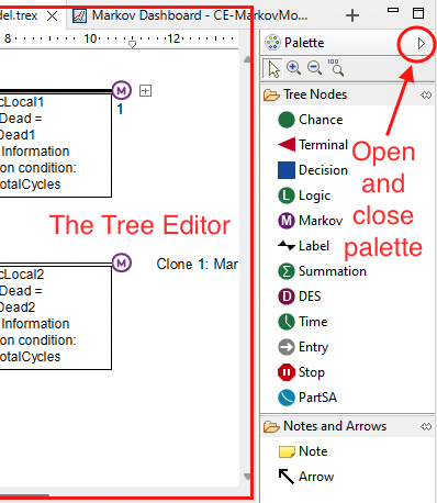
The Tree Diagram Editor consists of a modeling pane and a modeling palette (to the right-hand-side).
The Modeling Pane is the primary editing window, which contains the visual representation of the model. If the size of the model exceeds the size of the Modeling Pane, scroll bars will appear.
Several actions are performed within the Modeling Pane:
-
Add/delete nodes in the model.
-
Click on a node label to enter/edit label text.
-
Drag nodes to different places within the model.
-
Enter probabilities beneath the branches of chance nodes.
-
Select a node to change the perspective of node-specific views (Node Properties, Variable Definitions, etc.).
-
Etc.
The Modeling Palette contains tools for creating model structure and for viewing the model. Access the palette using the little arrow at the top right of the tree editor pane (circled in red below).
You can add branches to the right of any node by double-clicking on the chosen node. Double-click will typically add two branches if there are no existing branches and one branch if there are already existing branches.
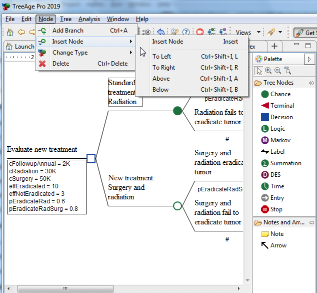
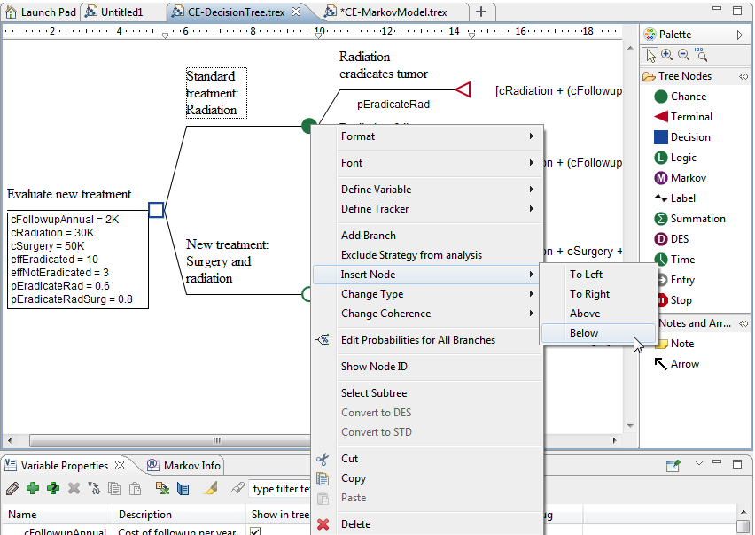
You can also use the toolbar to add branches and nodes into your model. You do this by selecting the location for the new branch and node, then use the toolbar icon for add a new branches. If you want to add nodes within the existing structure rather than as additional branches, then use the Insert Node option either via the Node menu or (with the node selected) right-click > Insert node menu option. Both of these options are shown in the figures below.
You can also drag nodes from the palette into the modeling pane to add a branch/node to the model. The location of the new node is controlled by where it is dropped within the model. The new node line and branch connector will appear (in red) as you drag a new node around the existing model.
At the top of the palette, the zoom in and out buttons allow you to zoom in and out within the modeling pane. First, click on the zoom in or out button in the palette, then click on the model in the modeling pane. The modeling pane will visually re-center and re-size based on your selection. To stop the zoom (in and out), just select the arrow from the top of the palette.
The note and arrow buttons allow you to add helpful notes and attach them to parts of your model. Click on either note or arrow button, then drag a note or arrow onto the model and use for making comments. You can turn the visibility of the comments on/off via the links on the Dashboard View.
Undo any actions which are wrong by using the Blue back arrow in the tool bar or choose Edit > Undo from the menu.